This article will help you decide where the optimal location is to put your Deno sensor(s) on the PV array
The most crucial step in achieving an excellent benchmark is installing the Deno sensor(s) in an appropriate location of the PV array. This article is intended to help PV system designers, project managers, and lead electricians understand how to properly specify and apply the Denowatts Digital Twin Benchmarking technology for each unique PV system.
First, it is important to understand where the Deno sensor is factored into the benchmarking equation, and what this sensor is used for.
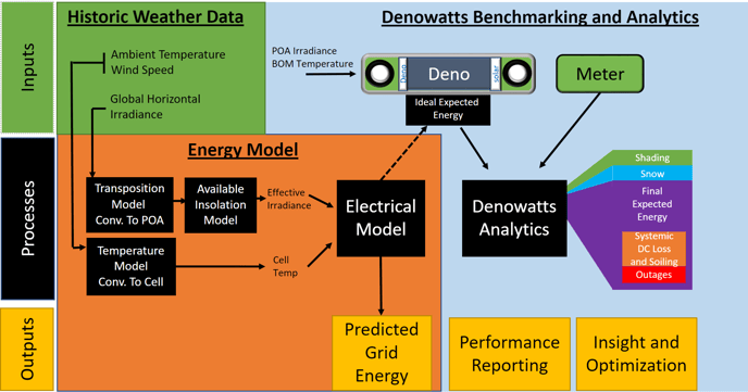
- This device measures the sunlight (irradiance) and back of the module temperature. From there the sensor inputs these variables into an electrical model to estimate the PV system's energy output.
- These onsite measurements create a real-time benchmark of the PV system's performance.
- The data collected from this sensor can be used in the system's capacity test report upon project completion.
"How the best benchmark is achieved?"
This sensor works in collaboration with advanced software in the my.denowatts.com portal to calculate a benchmark and automatically detect losses and outages. The software is designed with an ideal sensor placement and location in mind. Henceforth, locating this sensor with that ideal placement in mind will help the software provide the most accurate data.
It is best to think of this Deno sensor as a representative sample for the entire array. The sensor should experience the same sunlight and temperature conditions as the whole array as best as possible. Since the device is so tiny compared to the entire array, there are a couple of locating guidelines listed below that apply to all types of PV systems:
- Sensors must be placed in a location that will be free from shading during the summer and winter. Keep an eye out for shading from:
- Trees from the site perimeter
- Equipment poles outside of the perimeter of the site
- Equipment poles at the central equipment pad (GPS', Anemometers, etc.)
- Roof-top air handlers and other equipment.
- Sensors must be installed, so the Deno Sensor antennas are continuously in line of sight with the Gateway antenna, no more than 1/4 mile apart.
- This must be considered even more so on tracking systems as the moving parts can block the line-of-site during certain parts of the day.
- On a rooftop system, ensure the gateway antenna is on the rooftop for line-of-sight
- This must be considered even more so on tracking systems as the moving parts can block the line-of-site during certain parts of the day.
- Every PV system is unique and can vary in a multitude of aspects (physical size, shape, terrain undulation, etc.). Review system drawings to understand which locations near the gateway, are the sunniest, and most representative of the entire array
- If you have more than one sensor to locate, spreading them out (in suitable locations) best enables a more accurate averaged benchmark between the sensors.
- If you have more than one Plane-of-Array, put a sensor on each plane-of-array, or on plane-of-arrays with the most amount of DC capacity.
Expanding into more detail on topic #3, here are a few things to consider about each system type; Single-axis trackers, Fixed-tilt ground mounts, and roof-top systems.
Single Axis Trackers:
- Close as possible toward the center of the array without losing line of sight on antennas.
- Do not place the sensor on the first/last row of the array. Even more important if you have bifacial modules and an rPOA sensor to measure rear-side irradiance.
- rPOA sensors must be placed at least 2 modules from end of row
- Away from shading obstructions such as trees or equipment poles
- If the grade of the site is not even or has undulation:
- Place one sensor on a western roll and another on the eastern roll (Left and right deno in the picture below). This way the two irradiance readings are averaged together.
- If there is only one sensor, place it on the flat portion of the hill (middle deno)
-png.png)
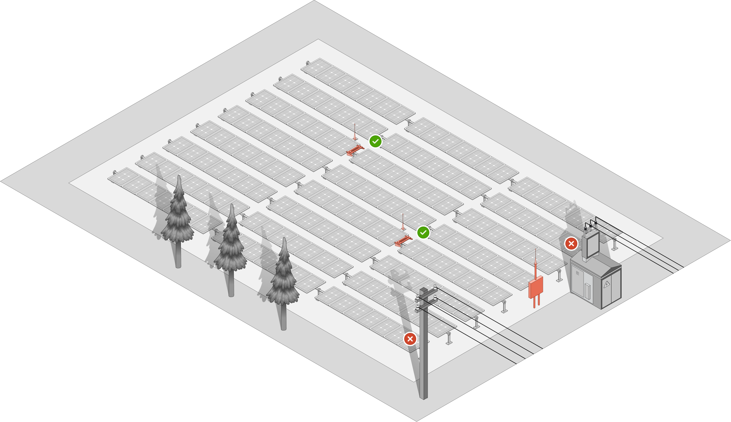
Fixed-Tilt Ground Mount:
- Away from shading obstructions such as trees or equipment poles
- Close as possible toward the center of the array.
- Place one sensor on a western roll and another on the eastern roll (Left and right deno in the picture below). This way the two irradiance readings are averaged together.
- If there is only one sensor, place it on the flat portion of the hill (middle deno) if the site's grade is not even or has undulation.
![]()
Array Undulation: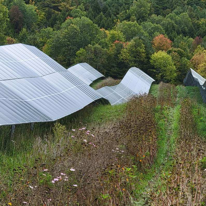
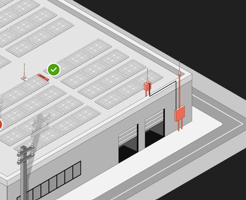
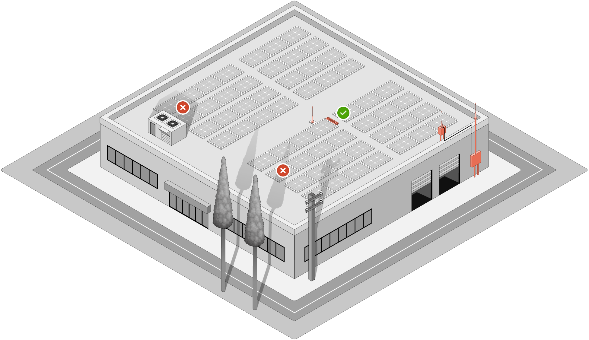
Fixed-Tilt Roof Top:
- Away from shading obstructions such as mechanical rooms or AC units.
- Close as possible towards the center of the array.
- Sometimes larger commercial roof-tops can have some slight variation in slope. Choose a location that is most representative of the entire array.
If any support/consulting is desired in checking for an adequate sensor location, please contact support@denowatts.com or call 978.309.6688 x 1