In this article, we will be walking through how to place and install Deno Antennas properly.
Introduction:
To complete the upgraded suite of Deno hardware, here comes the new high-gain Deno antenna
-
- 900 MHz, 5.8dBi, Omnidirectional Antenna
-jpg-1.jpeg)
Even with an upgraded antenna, installation practices still prove as the most important step to flawless radio communication on a site. In this article, we will be walking through proper installation tactics for the new Deno antenna and troubleshooting methods for improving sensor communications. Setting up a successful wireless communication network between the Deno sensors and Deno gateway is critical in the accuracy and functionality of your PV systems benchmark.
The Antenna:
-png.png?width=404&height=404&name=Antenna%206%20(1)-png.png)
The new Deno antenna is, by definition, an omnidirectional antenna, and by material, an 18" long, 1" diameter fiberglass cylinder with two mounting bracket options (pole mount or panel mount). This antenna helps improve communications in situations where perfect line-of-sight cannot always be achieved. (Though line-of-sight is ALWAYS strived for). There are two mounting options:
- Panel mounts attach the angled bracket to the antenna (shown above), and fasten between two solar panels using the single 2" washer and 3" bolt
- Pole mounts use U-shaped bolts and the rectangle bracket to fasten the Antenna to a piece of vertically mounted conduit or unistrut.
Deno antenna packages can have a little variability depending on where the antenna will be installed. The antenna locating/installation practices generally remain the same but fall into four separate use categories.
- Gateway - 1 antenna, pole mount
- GHI - still uses the original, shorter-gain omnidirectional "pig-tail" antenna.
- Tracker - 2 antennas per POA Deno sensor, panel mount
- Fixed Tilt - 1 antenna per POA Deno sensor, panel mount
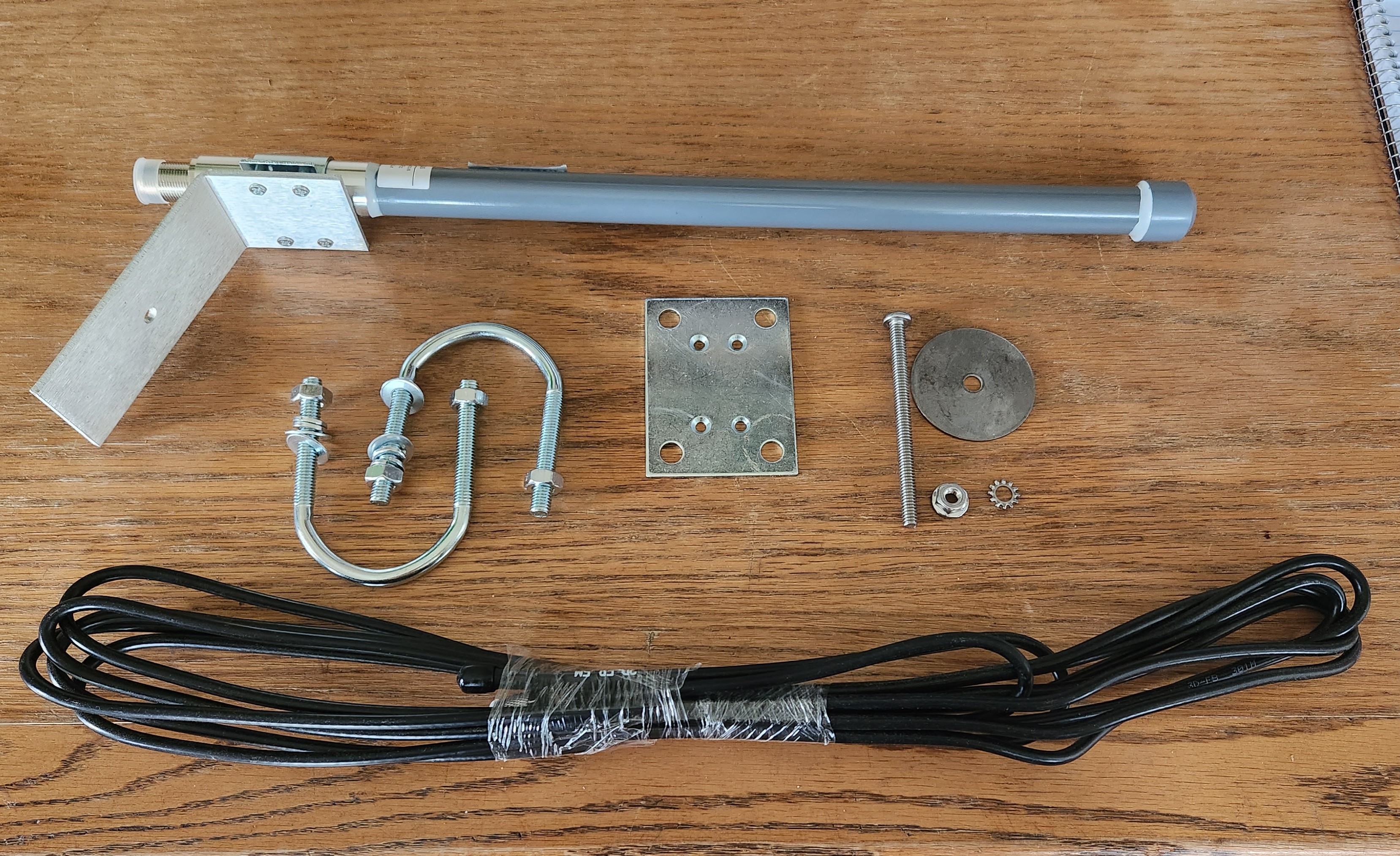
Hardware included:
- 18" Fiberglass Antenna
- 15'-coaxial cable per Antenna
- Mounting Hardware (any of the following)
- Gateway Mount (per gateway)
- (1) Antenna
- (2) U-bolts
- (1) Rectangle bracket and (4) screws
- Tracker Panel Mount (per POA Deno)
- (2) Antennas per POA Deno
- (2) Angled brackets + 2" washer and 3" bolt, nut and grounding washer
- (1) Antenna coaxial Y-connector
- Fixed Tilt Panel Mount (per POA Deno)
- (1) Antenna
- (1) Angled bracket with 2" washer and 3" bolt, nut and grounding washer
- GHI Mount
- (1) "Pig-tail" Antenna
- Gateway Mount (per gateway)
Installation:
Required Tools/Material:
- Ladder
- 7/16th crescent/combination wrench or deep socket with a racket
- Phillips-head screwdriver
- Strut or conduit (for gateways)
Gateway Antennas
The first antenna that will be installed on the system will be the Deno gateway antenna. This gateway antenna is installed where the Denowatts gateway is located, and the gateway is typically at the main pad within the DAS (data acquisition system) enclosure. Follow the steps below for a proper Deno Gateway antenna installation:
- Look for a location where the Deno antenna will be at least 4-6 feet away from other antennas on the DAS equipment rack.
- Mount vertical piece of strut/conduit securely to existing DAS rack, close to the enclosure where the Denowatts gateway is installed but out of the way of any GHI irradiance sensors nearby (e.g. other Denos)
- The top of the pole should be about 8-10 feet tall from the ground.
- Mount the antenna vertically to the top of the pole using the 2 U-brackets, and tighten the bolts appropriately.
- Connect the 15' coaxial cable to the antenna using the threaded connection point, finger-tight.
- Run the coaxial cable through any existing cable glands in the enclosure or carefully create a new punch out on the bottom for a new cable gland.
- Connect the RP-SMA screw connector to the Denowatts gateway and tidy up wire management with zip ties or sun-bundlers
Caution: if new punch-outs are made on the sides or tops of the DAS enclosure, you will be possibly infringing on 3rd-party warranties and exposing equipment to more risk of moisture intrusion
-png.png)
For best results, the Deno Antenna must be mounted 4-6 feet away from other antennas at the DAS pad:
- Cellular Antennas,
- Utility Meter Antennas
- Trackers Controller Antennas
- Tracker GPS Antennas
Example Gateway Antenna Installation:
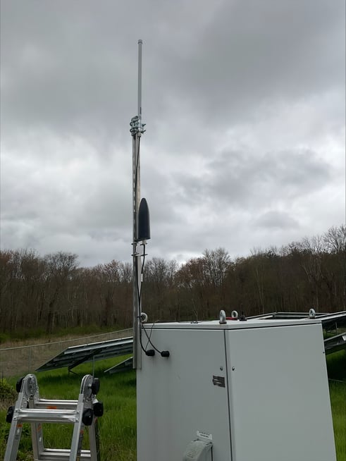
A couple of notes on this installation:
- The antenna is correctly mounted in a vertical position, 8-10feet off the ground.
- The antenna coaxial cable is neatly managed to the entry point.
- Cable gland entry points are not advised to be on the side of a DAS enclosure.
- Antenna proximity to cellular antenna OK but can be better.
Deno Antennas
After the gateway antenna is installed:
- Verify each sensor's communication to the gateway at a short range from the gateway antenna.
- (see the hardware installation guide for the full instruction set)
- Move the Denos to their final mounting locations in the array.
- (see the hardware installation guide for proper Deno sensor location instructions)
- Verify each sensor's communication with the gateway at their final mounting locations
Deno Sensor antennas typically follow the same rules as the gateway antennas with slight mounting variations
- Continuous Line-of-sight with Deno gateway antenna within 1200 feet
- 4-6 feet away from other antennas
- High up as possible
- Vertical orientation
- Avoid shading the very Deno sensor it is connected to by ensuring the sensor is 10 feet away from the antenna mount.
- Using angle-bracket and washer hardware, clamp in the gap in-between two solar panels.
- Avoid shading any PV cells
- Tidy up the remaining cable with zip ties or sun bundlers.
-png.png)
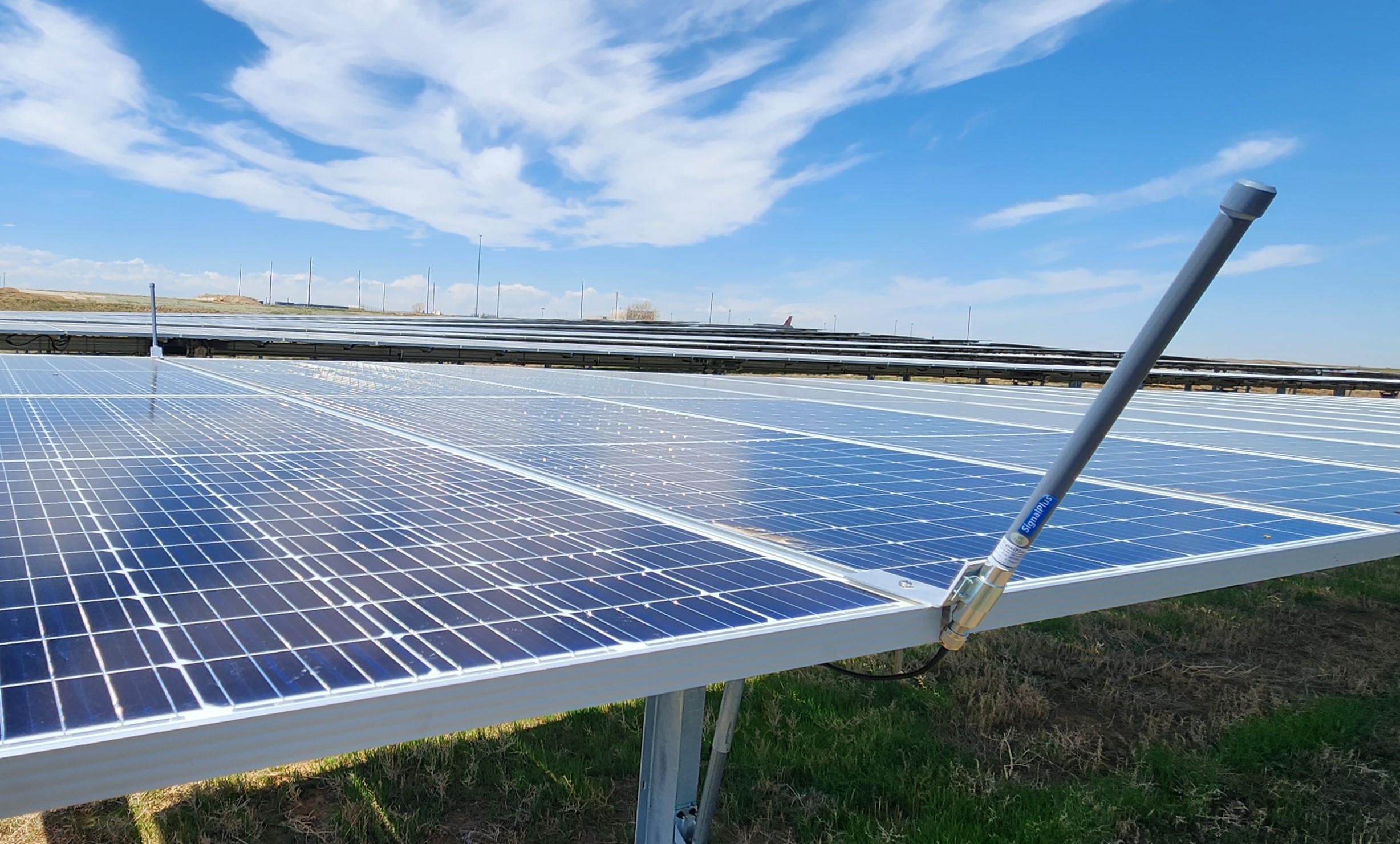
Fixed-Tilt Ground Mounts:
Example image of how to properly mount the antenna on a fixed-tilt tracker POA deno sensor.
-
- Mounted vertically on the top edge of the array in-between two solar modules.
- High up as possible
- The Deno sensor is far enough away to avoid shading
- Ensure no PV cells are being shaded by angle-bracket or washer
-png.png)
Tracking Ground Mounts:
Example image of how to properly mount the dual antennas on a tracker system POA deno sensor:
-
- (2) antennas, one on each edge of the array, ensures continuous line-of-sight as the array table tracks the sun throughout the day.
- Mounted vertically on either edge of the table in between two solar modules..
-
- The Deno sensor is far enough away from antennas to avoid shading.
- Ensure no PV cells are being shaded by the angle-bracket or washer.
-jpg.jpeg)
Roof-Top Installations:
Fixed-tilt rooftop systems sometimes have more variables to sort through to obtain proper line-of-sight for the best radio communications. Especially in the case where the Deno gateway is installed on the ground level, and the Deno sensor is installed on the roof-top. The graphic below depicts your options.
- Option A - Deno Gateway antenna is extended to the rooftop to create a line-of-sight with the Deno sensor antenna.
- Option B - Deno Gateway antenna is extended up the side of the building, mounted horizontally, 3' off the wall, and the Deno Sensor antenna is brought to the edge of the building to create a line-of-sight with the Deno gateway antenna.
- Option C - Entire Gateway is moved to the enclosure on the roof, enabling the Deno gateway antenna to have line-of-sight with the Deno sensor antenna.
- Option D - Deno gateway antenna is extended away from the building as far as possible. Ideally, the Deno sensor is placed on the side of the array where the gateway is on the ground, and its antenna is extended to the edge of the building as far as possible
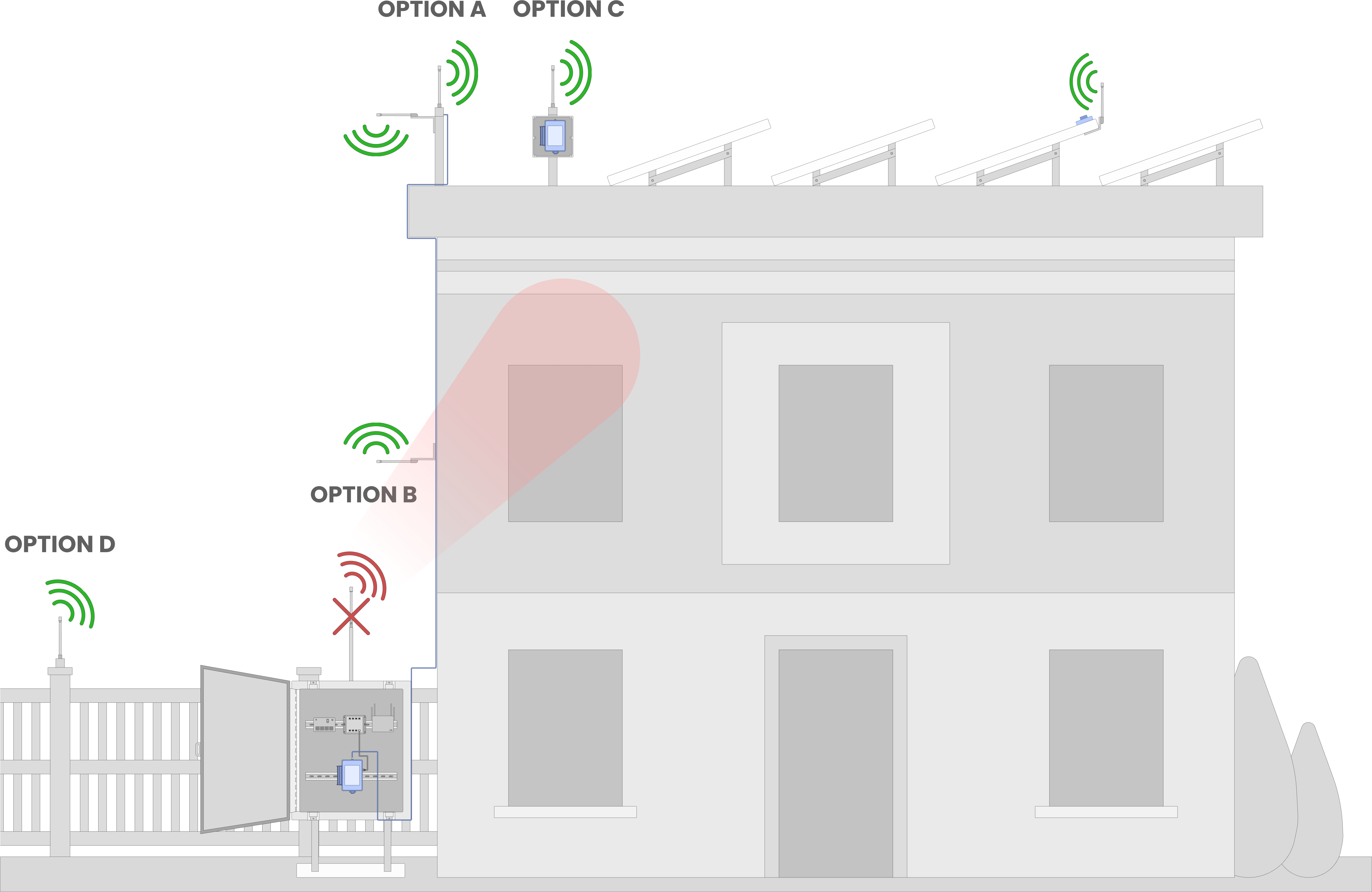
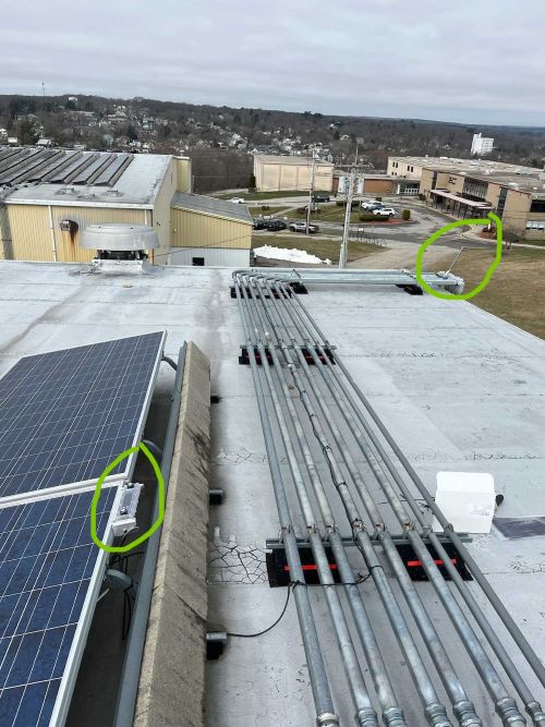
The example images below, combines option D along with moving the Deno Antenna to the edge of the building.
-jpeg-1.jpeg?width=433&height=1007&name=Gateway%20Antenna%20Upgrade%20(1)-jpeg-1.jpeg)
Troubleshooting:
If you find yourself dispatched to troubleshoot a Deno system communication issue use these simple troubleshooting steps to look for ways to improve communication.
- Look and see if the Deno Gateway antenna is 4-6 feet away from other antennas on the DAS rack.
- Make sure the deno Gateway antenna is as high up as possible
- Check that the connection to the Deno Gateway in the DAS is finger-tight
- Verify that the Deno gateway to the Deno sensor antenna maintain line-of-sight throughout the day and within 1200 feet.
- if there is only one antenna on a tracker POA deno, sometimes RSSI (Radio strength) will vary depending on the tracker angle and which edge the antenna is mounted to.
- if there is only one antenna on a track POA deno, ensure antenna is at the end of the row by the "main isle" of the site. with best line of sight to gateway.
- Check that the connection to the Deno sensors in the array is finger-tight
- Look out for any damaged antenna wiring with the antennas (little chips, extra sharp turn radius)
** Sometimes little adjustments will make big differences in radio strength and transmission success. Be patient if a few maneuvers become necessary to determine a sweet spot for communication. **
Online Verification
To see the results/impacts of your troubleshooting on the data, if you have access to a computer and a my.denowatts.com web portal, you can check the Denolink for each sensor and verify RSSI (Radio strength), and Radio Lag is within acceptable limits.
- -40 to -70 dBM is an acceptable range for RSSI.
- -40dbm being the best.
you want to strive for "lag time" readings under 10 seconds continuously
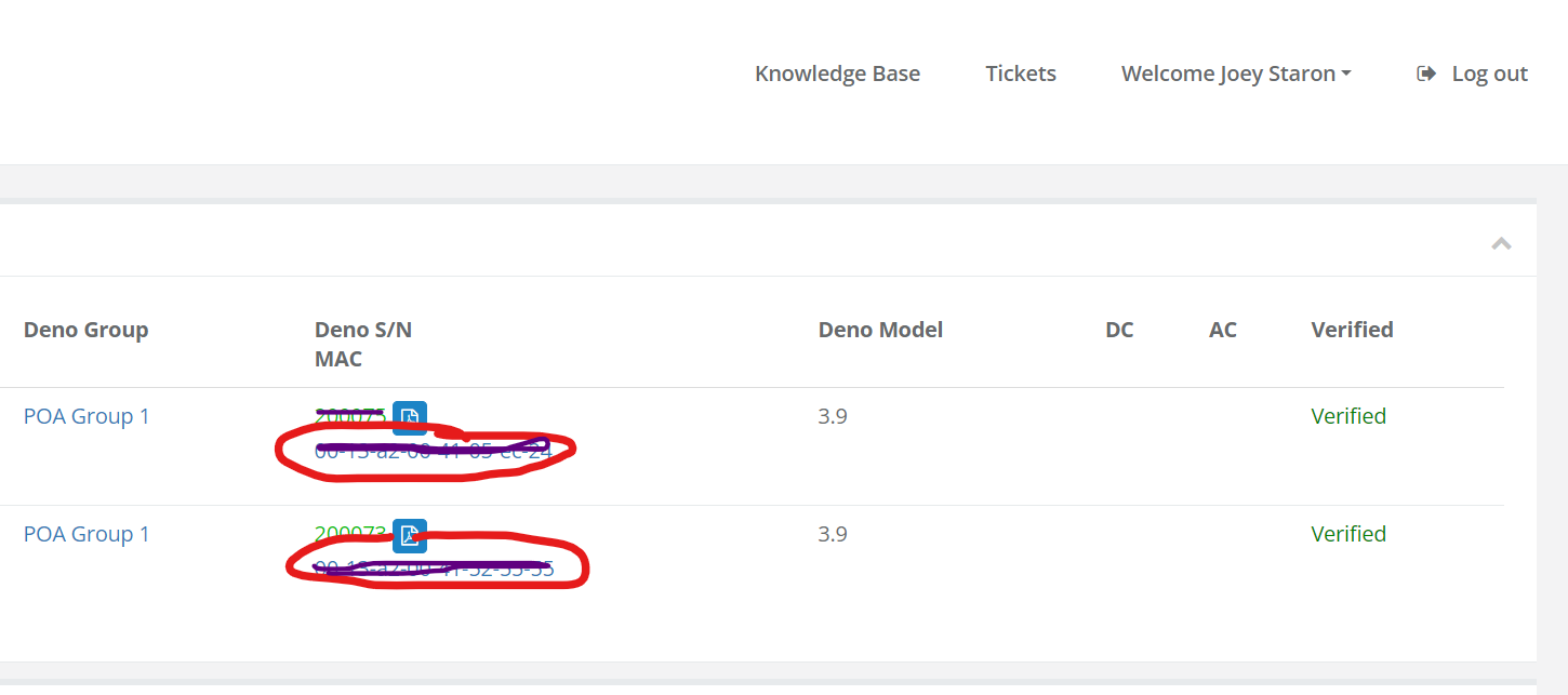
DenoLink (from site analysis or site list pages circled in red):
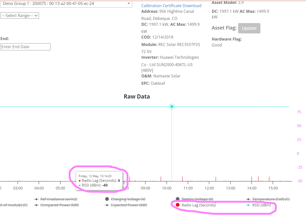
Denolink Graph:
The data in the example graph/screenshot below shows strong communication data. RSSI at -40dBm consistently, and radio lag continuously less than 10sec.
If anytime you are out on-site troubleshooting, please call our support line or email installation pictures to Denowatts support, and we can always help guide you through the rest of the process.
Email: support@denowatts.com
Phone: 978.609.6688 x1
Troubleshooting Examples:
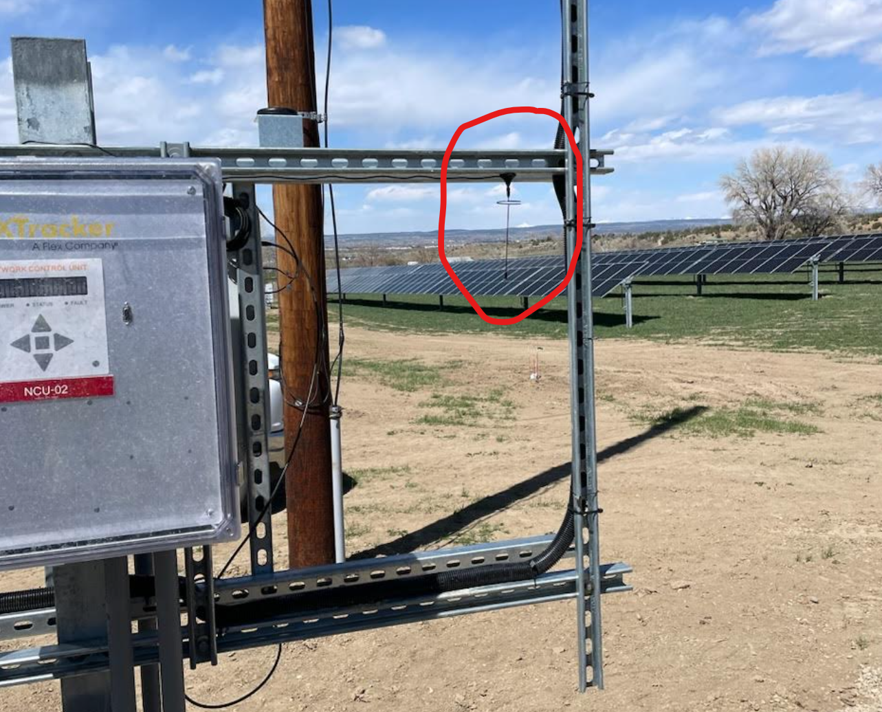
Problem 1: Antenna Proximity.
In this example, you will see an example of a Denowatts Gateway antenna mounted too close to a tracker network controller antenna. This resulted in very noisy-static-laggy-invalid data, and the own was unable to form a proper benchmark mark for a system capacity test.
-jpeg.jpeg)
There were quite a few other antennas located at this DAS pad, so finding a new dedicated spot for the deno antenna was tough.
%20(1)-jpeg.jpeg)
Solution:
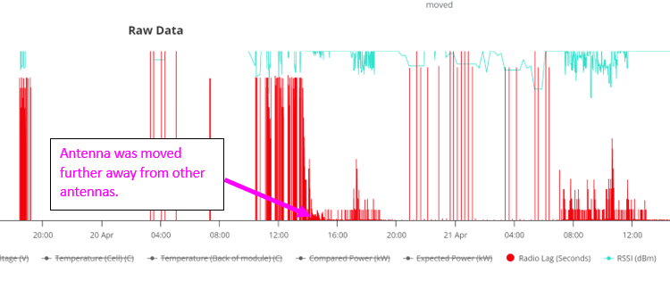
The antenna was moved to the best possible location on the DAS rack. This system had a very small rack that contained over six antennas installed on it. We did the best we could to get a solid connection and used the Denolink to verify the data after each antenna maneuver.
Below you can see the improvement in sensor radio lag after moving the antenna further away from the tracker controller antenna. This system is still experiencing some RF issues, but the readings are good enough to provide an accurate system benchmark.
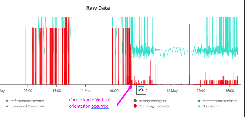
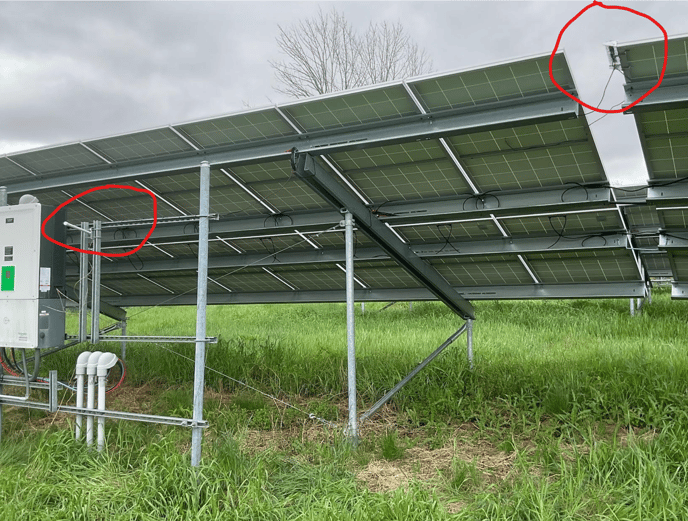
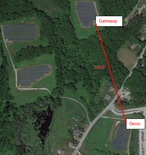
Problem 2: Antenna Oritentation
The picture below shows that the Deno sensor antenna is mounted incorrectly with a horizontal orientation and not very high up. Not to mention this specific antenna-to-antenna distance is about 1000 feet from the gateway. This was causing severe lag and power draw issues in the fixed-tilt POA Deno sensor.
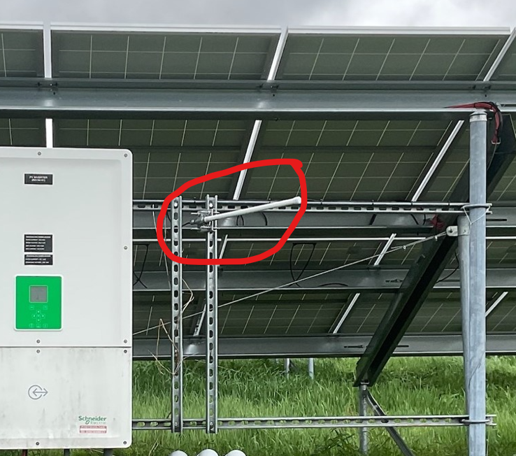
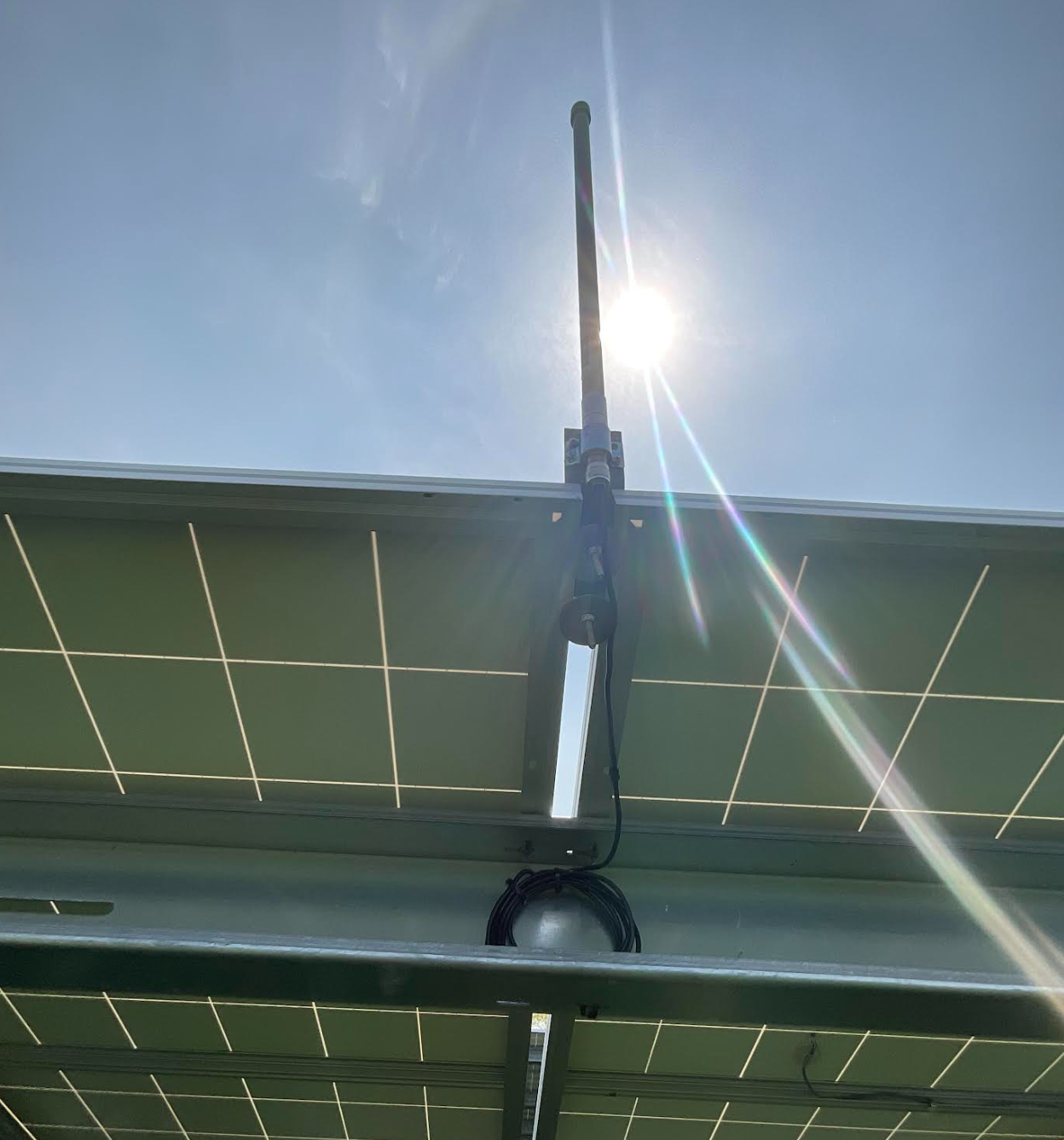
Solution:
The antenna was moved to a vertical orientation and mounted to in between two solar panels without shading the Deno sensor. Typically two panels over from the Deno sensor. Notice the tidy wire management of excess coaxial cable.
Below you can see the difference in radio lag and radio strength at the time of re-orientating from the Denolink in my.denowatts.com: